I will need to decode(1) the mark and space from the RTTY signal and also the CW tone so that signals can then be recovered and displayed.
The LM567 it's a nice available chip to do it and there are plenty of designs around, I just selected one, tweaked (some values I got from datasheet and are not the original from the schematic) and built:


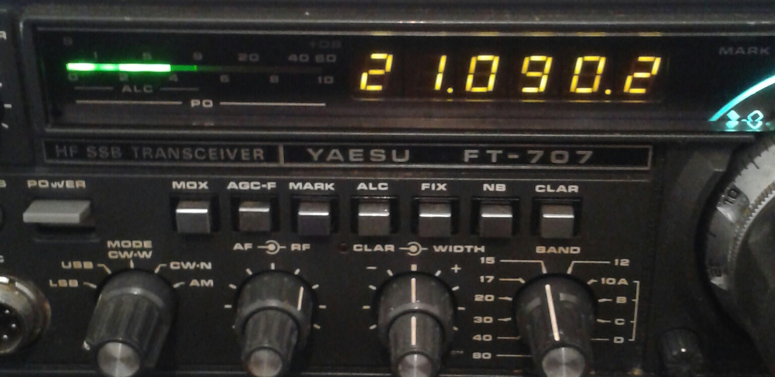
Then connected to the FT-707 headphone output and tested against live signals:
..worked first time.

For checking the lock frequency the best method is connecting a frequency counter to PIN 5 (PLL VCO) and count the frequency there (without input signals). I used the scope for the task!
Here's the range on mine using the 10K multi-turn adjustable resistor.
Low:

High:

And set for the moment:

That's it...have a nice week!
(1) - Technically it's note decoding since there is no encoding process, it will be more demodulating, since a carrier will be modulated by a signal, either mark, space or on off for CW.
No comments:
Post a Comment